Amiga Machine Code Letter IV - DMA Revisited
 Amiga Machine Code - Letter IV
We have reached Letter IV of the Amiga Machine Code course.
The CPU of the Amiga was the Motorola 68K. It’s speed grade at the factory was 8 MHz, yet when used in the Amiga, it was clocked to the odd 7.09379 MHz when outputting PAL video. Why was that?
Video signals for television in Europe are different from North America. Europe, and many other countries, uses the PAL system, while North America uses the NTSC system.
The Amiga was build so that the CPU was in sync with the video system. Such breed of computers are called “color-computers”, of which the Amiga was one of the last and most successful. There’s a great description here.
Quote from the link:
Why didn’t these color-computers just operate asynchronously and run the CPU at max spec, while the video system operated on color-clock? Because memory was at a premium in those days, so they used memory-mapped video. This was dual-ported in the simplest possible scheme, which required memory clocks be in lock sync with the video system.
The memory-mapped video in the Amiga is called chip-ram, and is shared with the CPU and the customs chips, including the video system. That is also the reason why all copper lists has to be in chip-ram. This makes the Amiga a synchronized multiprocessor architecture.
Because of the timing differences between PAL and NTSC, the Amiga 500 hardware comes with a crystal oscillator that is tuned to the video mode.
The image below shows the crystal oscillator on the Amiga 500 motherboard. For PAL it will be tuned to 28.37516MHz and that’s how you know that your hardware supports PAL.
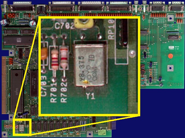
Notice that 28.37516 MHz divided by 4 is exactly 7.09379 MHz - the clock frequency of the Amiga 500 Motorola 68K for PAL. This keeps the CPU and the video system in sync.
Interleaved access
The Amiga is a synchronized multiprocessor architecture, where all chips share chip-ram. If all chips communicated with chip-ram without being synchronized, it would lead to bus contention. The equivalent of having several people speaking at the same time.
The Amiga avoids bus contention by synchronizing all the parts of the system to a common clock, but that only solves part of the problem. What if the 68K wanted memory fetched at the same time as some of the custom chips? That would lead to bus contention and to solve it, the Amiga uses interleaved access to memory.
The even clock cycles are available for the 68K, while the odd clock cycles are for the various custom chips. However, this is just a rule of thumb, deviations do apply.
Agnus contains the DMA controller that is responsible for time slot allocation for memory access to chip-ram. It takes several registers as input and uses those to determine how to allocate the time slots.
Here’s a diagram of the time slots, with my corrections printed on.
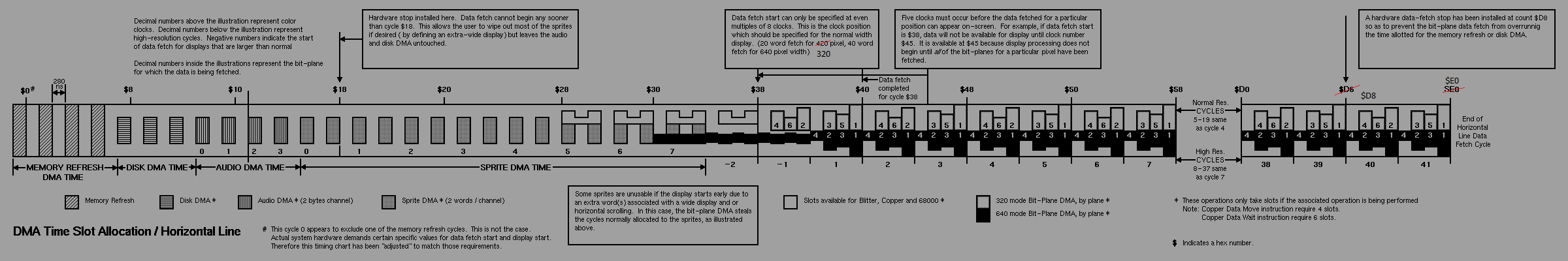
The diagram shows the time slot allocation for bitplanes 1 to 6. If we only have 4 bitplanes, then the 68K will be able to fetch from memory on all the even clock cycles. However, if we enable bitplane 5 and 6, then the bitplane willl steal cycles from the CPU. For highres mode with 4 bitplanes, there will be no cycles available for the CPU during data fetch.
Perhaps a bit oversimplyfied, this can be formulated as the more bitplanes, the slower the processor.
The data fetch period is determined by data fetch registers DDFSTRT and DDFSTOP.
These data fetch registers are indirectly determined by display window registers DIWSTRT and DIWSTOP.
In Letter IV the following rules are given:
LORES:
DDFSTART: ( HSTART / 2 ) - 8,5
round down to nearest $0 or $8.DFFSTOP: ( ( width in pixels / 16 ) - 1 ) * 8 + DDFSTRT
round up to nearest $0 or $8.
HIRES:
DDFSTART: ( HSTART / 2 ) - 4
round down to nearest $4 or $C.DFFSTOP: ( ( width in pixels / 16 ) - 2 ) * 4 + DDFSTRT
round up to nearest $4 or $C.
HSTART is the horisontal value of DIWSTRT. The hardcoded values 8,5 and 4 for DDFSTART is because the video hardware takes a couple of cycles to digest the DMA fetched data.
There are some slightly different formulas in the book Mapping the Amiga on page 510.
The bitplanes are continous arrays of memory that resides in chip-ram, so that it’s accessible by the video system. The location of the bitplanes are defined by the bitplane data registers BPLxDAT.
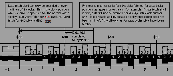
Notice that back in the DMA time slot diagram, bitplane 1 is always the last to be fetched. In the documentation, it says that fetching bitplane 1 triggers a parallel to serial conversion, that marks the completion of all bitplanes for that word of screen data.
This explains also why the diagram says that data fetched at $38 will first be available at $45. Because the fetch is first completed when bitplane 1 is fetched, and then we need to give the video system some time to “digest” the data.
Let’s look at some code
From Letter III we have the following code, which is a kind of warm-up for all of the new insights in Letter IV.
; Letter III initial bitplane program
start:
move.w #$01a0,$dff096	; DMACON, disable bitplane, copper, sprite

move.w  #$1200,$dff100  ; BPLCON0, enable 1 bitplane, enable color
move.w  #0,$dff102	; BPLCON1 (Scroll)
move.w  #0,$dff104	; BPLCON2 (Sprites, dual playfields)
move.w  #0,$dff108	; BPL1MOD (odd planes)
move.w  #0,$dff10a	; BPL2MOD (even planes)

move.w  #$2c81,$dff08e	; DIWSTRT
move.w  #$f4c1,$dff090  ; DIWSTOP (enable PAL trick)
move.w  #$38c1,$dff090  ; DIWSTOP (PAL trick)
move.w  #$0038,$dff092  ; DDFSTRT
move.w  #$00d0,$dff094  ; DDFSTOP

lea.l   copper,a1
move.l  a1,$dff080      ; COP1LCH pointet to the copper list

move.w  #$8180,$dff096  ; DMACON  enable bitplane, enable copper
wait:
btst    #6,$bfe001	; wait for left mouse click
bne     wait

move.w  #$0080,$dff096	; restablish DMA's and copper

move.l  $4,a6
move.l  156(a6),a1
move.l  38(a1),$dff080

move.w  #$80a0,$dff096

rts

copper:
dc.w    $2c01,$fffe	; wait($01, $2c)
dc.w    $0100,$1200	; move to $DFF100 BPLCON0, use 1 bitplane, enable color

dc.w    $00e0,$0000	; move to BPL1PTH, bitplane pointer high
dc.w    $00e2,$0000	; move to BPL1PTL, bitplane pointer low

dc.w    $0180,$0000	; move to COLOR00, black
dc.w    $0182,$0ff0	; move to COLOR01, yellow

dc.w    $ffdf,$fffe	; wait($df, $ff) - enables waits > $ff vertical
dc.w    $2c01,$fffe	; wait($01, $2c) - $2c is $12c

dc.w    $0100,$0200	; move to $DFF100 BPLCON0, disbale bitplanes, enable color
                        ; needed to support older PAL chips.

dc.w    $ffff,$fffe	; end of copper
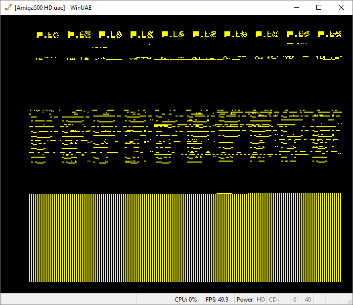
The letter explains the code, so I won’t provide more comments than those left in the code. However, the gist of this code is to draw a lores image using one bitplane that maps into a color table with two colors - black and yellow.
The code does not allocate space for the bitplane, instead it points bitplane 1s pointer to $000000. So what we end up seeing is an image of memory in the address space from $000000 to $002800, assuming the screen is 320 x 256.
Try running the program and move the mouse around. You should see some changes in the yellow dots, where the mouse is memory mapped.
In the next post, we will take a closer look at some of the other programs in Letter IV.
Previous post: Amiga Machine Code Letter IV
Next post: Amiga Machine Code Letter IV - More Code.