Amiga Machine Code Letter V
 Amiga Machine Code - Letter V
We have reached Letter V of the Amiga Machine Code course.
This letter is all about sprites and a few extra machine code instructions, and the instroduction of the stack. Let’s start with the extra machine code instructions and then look at some code.
A new way to move
The letter introduces a new addressing mode called address indirect with indexing and displacement. The addressing mode is listed in the 68K opcode sheet and can be used by various instructions e.g. like move.
move.w (A1, D1), D2 ; fetch data in address A1+D1 and put it in D2
This instruction will fetch the data in address A1+D1 and put it in D2.
There is also a variant with a displacement.
move.w 10(A1, D1), D2 ; fetch data in address A1+D1+10 and put it in D2
This instruction will fetch the data in address A1+D1+10 and put it in D2.
In the 68K manual and opcode sheet, the syntax is a little different.
(d, An, Xi) Address register indirect with displacement, and address
            register indirect with indexing and displacement.
I won’t go through the hoops of showing how to derive the opcode, as I have done previously, since it’s just more of the same stuff.
It’s a good exercise, however, to see the binary output from Seka and try to deduce how it ties together with the opcodes.
Hint: In the opcode sheet, consider the Brief Extension Word together with the move instruction. The Brief Extension Word is used for two of the 68K’s addressing modes, which the above is one of. 📝
When I tied the instruction together with the opcode, I noticed that I should limit the displacement to $FF, since anything above will be trunctated. The letter didn’t mention this, I guess to avoid getting stuck in the rabbit hole of details 🐰.
Ok, moving on (pun intended)
Logical shift left/right
This twin set of instructions shifts bits of the operand left or right. For details view the Motorola 68000 Reference Manual on page 4-91. The bit that is shifted in is always 0.
move.b #%00101100,d0
lsl.b #1,d0 ; shifts the byte 1 position to the left
            ; %01011000
The instruction can also be found in the opcode sheet as LSd where d is L/R. Naturally, a right shift works in the opposite direction of left.
The carry bit in the status register, recieves the bit shifted out of the operand. Do check the reference manual, there are limits on how data in memory is handled, compared to data in registers.
move.l #%0110 0100 0101 1010 0100 0011 0110 0100,d0
lsl.w #1,d0 ; shifts the bits in the first word 1 position to the left
; %0110 0100 0101 1010 1000 0110 1100 1000
If you really want to see the opcode, look in the opcode sheet or in the reference manual page 4-192. The latter, explains it with more context.
The stack
Next machine code instruction is BSR or Branch to Subroutine. In order to make any sense of it, we have to know what a stack is.
The stack is like a stack of plates in a plate dispenser. The first plate to push on the stack is also the first you pop off the stack. We also call this a LIFO buffer last in first out.
In the context of the Amiga, we use the stack to save state, and to do something new that requires it’s own state. When we are done with whatever we were doing, we simply pop off the old state from the stack, to reastablish the old state.
Make sure to read Letter V, and follow the illustrated example.
The stack is governed by a stack pointer (SP), that points to the top of the stack. This stack pointer is located in the address register A7.
To save state, we typically want to push many registers on to the stack. We do this push by using a specialized move instruction called movem which move multiple registers.
movem.l d0-d5,-(a7) ; push d0 to d5 onto the stack and predecrement SP
The illustrated stack example in Letter V left me puzzled, somehow I wanted the stack pointer to be somewhere else 😕.
When faced with something murky, the best strategy is to try it out in practice. The program below is just such an attempt.
; mc05stack
start:
move.l a7,a0        ; save SP in a0
move.l #$10,d0      ; move $10 into d0
move.l #$20,d1      ; move $20 into d1
movem.l d0-d1,-(a7) ; push d0-d1 on stack
move.l a7,a1        ; save SP in a1
clr.l d0            ; clear d0
clr.l d1            ; clear d1
movem.l (a7)+,d0-d1 ; pop d0-d1 from stack
move.l a7,a2        ; save SP in a2

rts                 ; return from subrutine
The code is trivial, we save our initial SP in a0, and then move some values into d0 and d1. Then we push those onto the stack and saves the SP in a1. We then clear d0 and d1, and reestablishes the state by poping the stack, which sets d0 and d1 to their values before the clear. We then save the SP in a2.
I ran this program in Seka and got the following output:
d0 = $10, d1 = $20
a0 = $c49bb0, a1 = $c49ba8, a2 = $c49bb0
We push two longs onto the stack, which decrements the stackpointer by $8. We see that a0 - $8 = a1, which is exactly as expected.
But what data is the stack pointer pointing at? To check this, start up the debugger. Here’s an image of the debugger just before we save the stack pointer in a1.
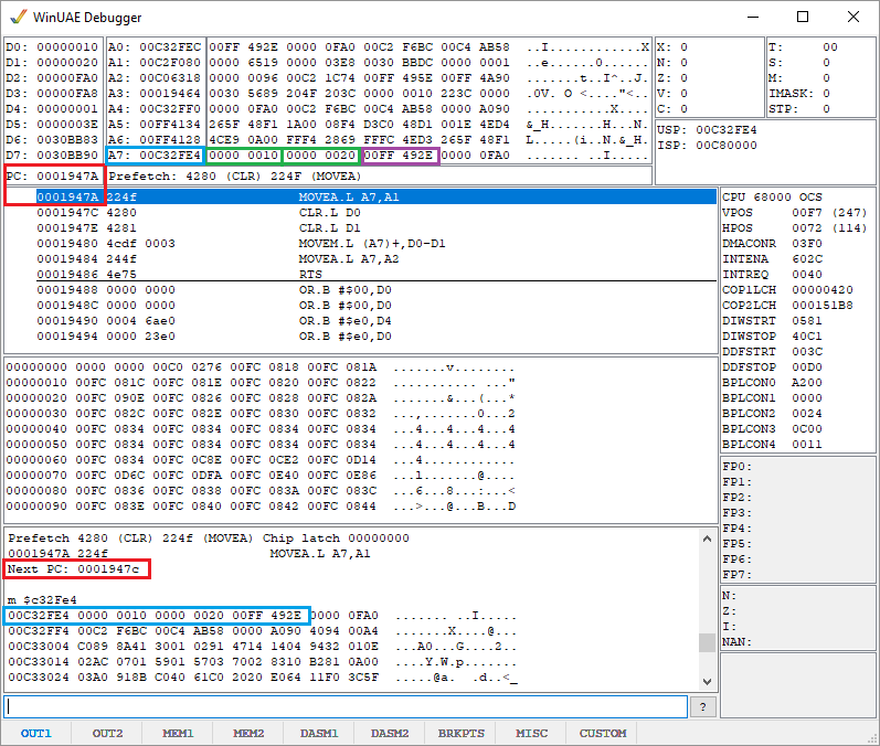
The green boxes shows the values we pushed on the stack. The blue box by a7, shows our stack pointer SP, and we see it repeated down in the memory dump. The SP points to $c32fe4 that contains $10 because we pushed d0 and d1 together as as set with movem. How would this had looked if we had pushed them seperatly? You figure it out 😃
hint: you can just use a move to push or pop a single value on the stack 📝
The red boxes show the program counter - it has a connection with the purble box. Step through the program and see what happens when we clear d0 and d1, and then later pop the stack.
Ok, moving on to the last line in the program, rts, return from subroutine.
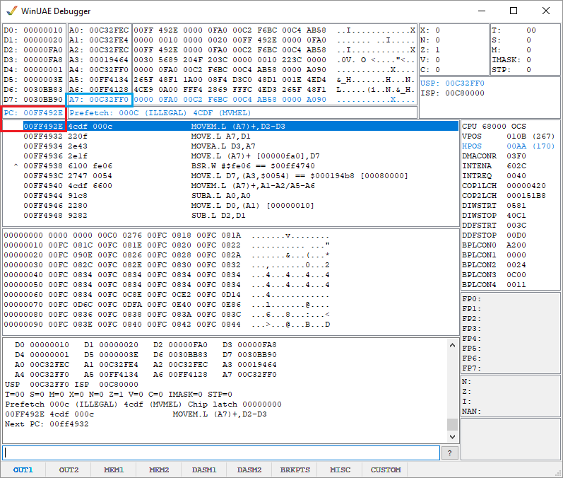
Notice how the SP went from $C32FE4 to $C32FF0, that’s a difference of $C, or 12 bytes, or 3 longs. Two of these longs where from when we pushed d0 and d1 onto the stack. The last long is the return address that rts uses to send us back where we came from. That’s the purble box in the first image. The second image shows that the program counter PC has now been updated to point to that address.
If we somehow screw up our stack arithmatic, I guess we could send the program counter to places it shouldn’t go, when we call rts. In higher level languages, switching between stack frames are done by the compiler. Here at the machine level, we have to do it ourselves.
Branch to subroutine
With knowledge of the stack, we can now make better sense of BSR. We use this instruction to go to a subroutine. It’s the basic equivalent of a function call in higher level languages. The general gist is the following
bsr routine  ; go to routine
...          ; code goes here
rts          ; return from subroutine

routine:     ; label named routine
...          ; code goes here
rts          ; return from subroutine
Letter V encourage you to play a little with BSR to get a feel for it. I did this, and you should do it too. It’s good advice to get your hands dirty.
What I found, was that we have to pay attention to stack arithmatic here. If I push something on the stack in a subroutine, I better remember to pop it before I call RTS. Remember that the stack also contains the return address for the program counter.
In higher level languages, we typically don’t worry about the stack or the stack pointer, since all that bookeeping is done by the compiler.
The BSR and RTS instructions, will enable us to define subroutines that can divide our assembler code into general reusable parts.
Next post
In the next post, I’ll write more about sprites and also look at the program examples in Letter V.
Previous post: Amiga Machine Code Letter IV - More Code
Next post: Amiga Machine Code Letter V - Sprites.