Amiga Machine Code Letter II - Part 1
 Amiga machine code - letter 2
We have reached letter II of the Amiga machine code course. This letter introduces some basic but very important stuff - the DMA channels and the copper.
I will go thrugh this letter a little bit out of order. For me, it’s more logical to start with the introduction to the assembler instructions move, add, sub and lea.
In the deep dive of letter I, we saw how the opcode for move looked like.
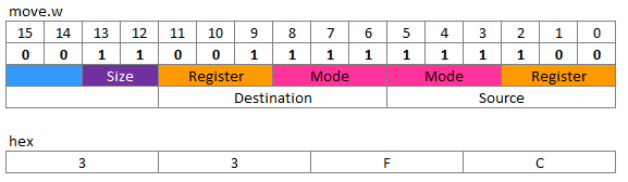
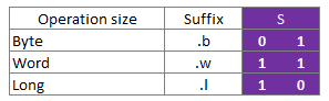
The destination bits determines the operation size of the move, i.e. what size of data to move. We can move a byte, a word (two bytes), and a long (four bytes).
And for the register and mode we can choose from this list of addressing modes.
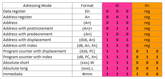
If my combinatorials aren’t failing me, that amounts to 432 different opcodes just for the move instruction. However, some combinations are illegal, e.g. we can’t move an immediate value to an immediate value.
move.w #$4000, #$10 ; illegal operand
It’s good that we have the assembler to keep track of the opcodes. However, looking at the opcodes, is no futile exercise, since it gives a sence of the concepts at the lowest level of Amiga programming stack.
Take for instance the above table of addressing modes, with it’s twelve addressing modes. In Letter II, we are introduced to two of the addressing modes: Immediate addressing, and Direct addressing.
Immediate Addressing
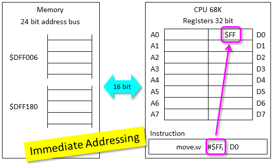
With immediate addressing the move opcode will instruct the CPU to move the value in the first operand of the instruction to the given destination defined in the second operand. The immediate operand is specified with a # and is always the source operand.
Here’s an example:.
move.w #$FF, D0
The number $FF is moved into the register D0. This instruction can be executed entirely inside the CPU.
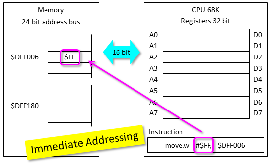
Another example:
move.w #$FF, $DFF006
The instruction moves the number into an address in memory. This requires the CPU to write the value into memory which has to be done through a databus that is only 16 bit wide. In this case we are only moving a word, but a long would require two writes. This operation is somewhat slower than the previous example.
Direct Addressing
The Amiga Letter II introduces the concept of direct addressing. The mode is not found in the above addressing mode table, which is a bit confusing.
I figure that Direct Addressing means the following address modes from the table when used on the source operand.
- Data register
- Address register
- Absolute short
- Absolute long
There’s a good description of the different addressing modes in chapter 4 of the book Amiga Assembly Language Programming (page 26).
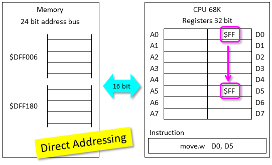
The first example is a variant that uses an Address register mode on the source oprand of the move instruction.
move.w D0, D5
The example above moves a word from one register to another, without reading from memory. A rather fast instruction.
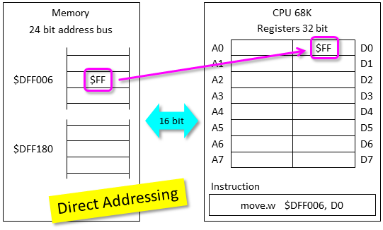
The second example uses the Absolute long addressing mode on the source operand of the move instruction.
move.w $DFF006, D0
The value stored at memory address $DFF006 is fetched and moved into data register D0, inside the CPU. Notice how data is moved accrosss the 16 bit databus between memory and CPU. If we moved a long this opreation would have required two fetches from memory.
The third example also uses the Absolute long mode on the destination operand of the move instruction.
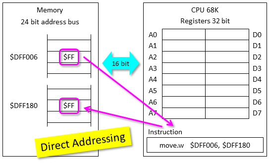
The value stored at memory address $DFF006 is fetched and then written to memory address $DFF180. This instruction requires the 16 bit databus between memory and CPU to be crossed twice, which makes this instruction slower than that in the previous example.
Add and Sub
The next instructions are add and sub. As their name implies, they add and subtract numbers. The opcode construction is somewhat complex, and I wont go through it here. Take a look at the 68k opcode sheet here.
Lea
This instruction is short for Load Effective Address and can take an address and load it into an address register. Let’s take a look at a non-functioning program, with it’s hex codes added in the comments. The hex codes can be seen by assembling the code with the v option.
lea.l  copperlist, a1 ; 43 F9 - 00 00 00 08
rts                   ; 4E 75

copperlist:
dc.w   $2C01,$FFFE    ; 2C 01 - FF FE
From the opcode table, we see that the lea instruction is constructed like this:
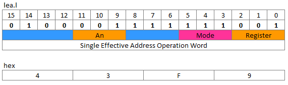
This tells us that lea can do address calculations on any mode in the address table above - Address with postincrement and predecrement are excluded ( source). Don’t worry, the assembler will spot any faults and refuse to assemble the program.
We also see that lea will move 32 bits into an address register - data registers can’t be used. Amiga memory addresses are 24 bits, so the most significant bit of the address register is not used.
So what does lea do? In our progamme above, it takes the address of the label and put’s it into address register a1. Notice that it adds a delta from the current address to the label, which is $000008.
The value $08 is a possition independant delta to the address of the copperlist. Since the program can be placed at different memory locations at runtime, the lea instruction also adds the program counter to the delta value to get the precise memory address.
Here is a hex dumb from inside the Seka assembler of the program, when placed in memory.
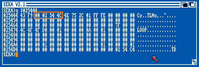
I have highlighted the address that lea is loading into the a1 register. The address is $02544C and not $000008 as seen in the code listing. That’s because the code listing shows the delta value, before the value of the program counter is added.
The program counter is at $025444 and if we add $000008 we get exactly $02544C, which is were the copperlist starts in memory. This is determined runtime as we don’t know beforehand exaclty where the operating system will place the program.
Some additional explaination of lea can be found here.
Wrap up
This post has already been long enough and we have covered a lot of ground, but we have not completed Letter II yet. We still need to look at the very important concept of Direct Memory Access (DMA), which is how the auxillary chips Paula, Agnus, and Denise can access memory and do some work without the CPU. This was an essential hardware construction that enabled the success of the Amiga.
Previous post: Amiga Machine Code Letter I - Hint
Next post: Amiga Machine Code Letter II - Part 2.