Amiga Machine Code Letter II - Part 2
 Amiga machine code - letter 2
We continue where we left of in the previous post. Letter II can be found here.
DMA channels
DMA stands for Direct Memory Access and the channels allows the Paula, Agnus, and Denise coprocessors to communicate with memory, without involving the CPU. This hardware design is a key feature of the Amiga, which made it the multimedia machine of the late eighties and early ninetees.
An important limitation of DMA is that the coprocessors only can access chip-mem in the memory area from $000000 to $07FFFF (Amiga 500). Hi-mem can thus only be accessed by the CPU. Hi-mem is also called Fast-mem, since the CPU does not have to share access to that memory area with the other co-processors.
The CPU is needed for setting up and starting the DMA channels, before the coprocessors can start the communication through DMA. When that happens, the CPU is free to do other tasks. That’s why e.g. playing sound does not burden the CPU, because that work is handled by the audio chip called Paula.
The DMA channels of the Amiga
| Type | Number of Channels |
|---|---|
| Disk | 1 |
| Audio | 4 |
| Sprite | 8 |
| Bitplane | 6 |
| Copper | 1 |
| Blitter | 4 |
The process of reading data from a disk can be broken down to the following steps.
- The CPU allocates a buffer and starts the disk motor
- The CPU initializes the disk DMA
- Paula uses its floppy disk controller to read data. The CPU is now free to do other stuff.
- Paula sets an interrupt when finished.
The Amiga can use all it’s 24 DMA channels at once, and that unloads the CPU from a lot of work.
DMA Time Slot Allocation per Horizontal Line
Access to chip-mem, from the CPU and all the coprocessors, is controlled by the Agnus coprocessor. It schedules access to chip-mem using the position of the video beam. For every line drawn on the monitor, there is allocated a certain amount of cycles for the different DMA channels.
Agnus access policy to chip-mem is somewhat complex and it prioritize some DMA channels over others. Letter II includes a figure of how the time slot allocation works.
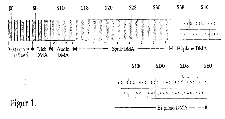
The simple rule is that Agnus allocates the odd clock cycles to the coprocessors, while the even cycles are allocated to the CPU. This means that using DMA channels typically does not block the CPU from accessing chip-mem. However, special rules can be applied, where some DMA channels are prioritized and the CPU will become blocked. More about that in a later post.
According to Letter II, the even clock cycles are available not just to the CPU but also to the Blitter and Copper. If the audio DMA is not used, then it’s odd cycles will be available to the CPU, Blitter, and Copper too. But that’s a complexity I won’t go into now.
The Copper
The Copper is short for co-processor and is a part of Agnus. It is a finite state machine that can be programmed using a stream of instructions called a copper list. The copper list has three instructions move, wait, and skip.
The Seka assembler does not support copper instructions mnemonics, so the opcodes has to be written manually in the copper list. Let’s take a look at the copper program from Letter II, and then follow up with an explaination.
start:
move.w	#$01A0, $DFF096
lea.l	copperlist, A1
move.l	A1, $DFF080
move.w	#$8080, $DFF096

wait:
btst	#6, $BFE001
bne	wait

move.w	#$0080, $DFF096
move.l	$04, A6
move.l	156(A6), A1
move.l	38(A1), $DFF080
move.w	#$81A0, $DFF096
rts

copperlist:
dc.w	$9001, $FFFE  ; wait for line 144
dc.w	$0180, $0F00  ; move red color to $DFF180
dc.w	$A001, $FFFE  ; wait for line 160
dc.w	$0180, $0FFF  ; move white color to $DFF180
dc.w	$A401, $FFFE  ; wait for line 164
dc.w	$0180, $000F  ; move blue color to $DFF180
dc.w	$AA01, $FFFE  ; wait for line 170
dc.w	$0180, $0FFF  ; move white color to $DFF180
dc.w	$AE01, $FFFE  ; wait for line 174
dc.w	$0180, $0F00  ; move red color to $DFF180
dc.w	$BE01, $FFFE  ; wait for line 190
dc.w	$0180, $0000  ; move black color to $DFF180
dc.w	$FFFF, $FFFE  ; end of copper list
The program initializes the copper DMA channel and dispatches the copperlist to the copper, and waits for the user to press the mouse. When the left mouse button is pressed, it then reestablish the OS copperlist and exits. It produces the following output.
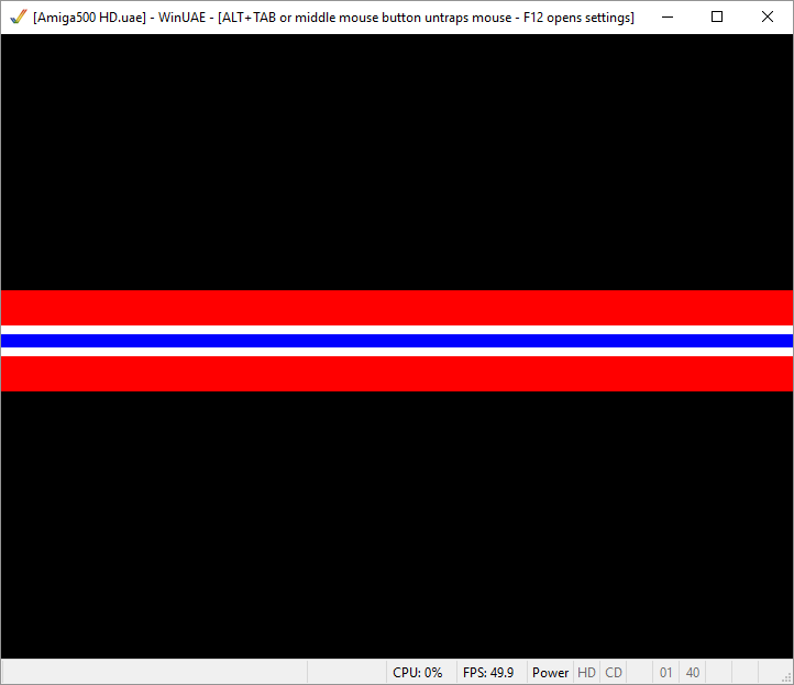
The copper is a state machine that executes it’s copperlist every time the screeen is redrawn. It remembers it’s state from the previous screen draw, which is why setting the background to black at the end of the copper list is remembered at the top of the screen.
We can verify this by removing the line that sets the color to black in the copperlist. The black areas should become red.
The register address $DFF180 is called COLOR00 and sets the value of color table 0, which is the background color.
Copper move
The move instruction consists of two instruction words. It moves data from memory to a register destination.
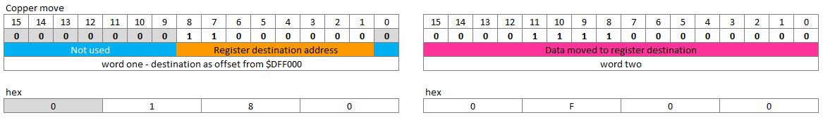
The register destination are given as an offset to $DFF000. This is the address space for custom chip registers. There’s also an explaination of this over at copperhade.org.
Copper wait
The wait instruction also consists of two instruction words. The first intstruction word tells the copper to wait until the specified video beam counters is reached or greater. The second instruction word specifies a mask that tells the copper which bits of the beam counters to use when making the comparison.
When the copper waits, it’s not using the databus, which frees memory cycles to be used by the CPU or blitter.
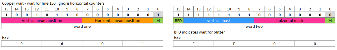
In the figure above, we wait for line 150, and only compare with all the bits for the veritcal beam counter as specified by the mask.
In the above program we use the waits so that only the vertical beam position is specified, and a mask that says to use all bits in the comparison.
Letter II does not dive into the use of masks, and there is a lot of things not explained, like e.g. the BFD bit in the second instruction word of the wait instruction.
The Letter concludes with the remark that we have only scratched the surface about what the copper is able to do. To understand more, we need to wait for the next letters to arive 😃
Here’s an optional detour from the course, that takes a look at reverse engineering.
Feel free to skip. It’s not required reading for the next letters.
Previous post: Amiga Machine Code Letter II - Part 1
Next post: Amiga Machine Code Letter III - Copper Revisited.