Horizontal Sine Shifting
 Amiga Machine Code - Letter XII
One of the classic demo effects, of all time, is horizontal shifting using a sine wave. This effect is easy to code on the Amiga, using Copper instructions to deliver timed updates to the custom chip registers.
In the following, we are going to look at how this is done, and explain a litle bit about how the Amiga works along the way. This post is inspired by Letter XII of the Amiga Machine Code Course.
The Amiga was one of the last color computers were everything was in tune with the video display system. This syncronization is reflected all the way down to the DMA time slot architecture, and it’s an essential part of the horizontal sine shifting effect.
It’s through the DMA bus, that all data from chip memory is transfered between the various hardware sections. Only a master can initiate data transfer over the bus, so if two masters try to use the bus at the same time, bad things will happen. To prevent this, a mechanism is added to the hardware, which determine which master gets to use the bus. This mechanism is called bus arbitration.
Not counting other expansion devices, the Amiga 500 has two masters. One master is the 68000 CPU and the other is (Fat) Agnus residing in the custom chip section. The bus controller is called Gary.
In a way, the Amiga is not just one, but two computers, with the bus arbitration controller as the conductor that directs the orchestra 🎻 🎺

This design allows the CPU to delegate a lot of work to the custom chips, and gave the exceptional performance that the Amiga delivered to the home computer scene.
The horizontal scrolling effect uses this design quite effectively. It lets the CPU write sine data into the Copper list, that is stored in chip ram, while delegating the horizontal shifting to the custom chips. Now, let’s see how it’s done 😃
The Wave Program
The code for this effect is stored in the wave folder of DISK2 and the program is called wave. It produces a horizontal wave by using the Copper to set the horizontal scroll for selected scanlines.
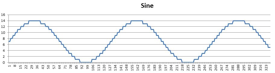
The wave program will produce an output like this:

If you want to try it yourself, then type the following into K-Seka to assemble the program and load the data files into memory:
SEKA>r
FILENAME>wave
SEKA>a
OPTIONS>
No errors
SEKA>ri
FILENAME>sine
BEGIN>sine
END>
SEKA>ri
FILENAME>screen
BEGIN>screen
END>
SEKA>j
Let’s take a closer look at the data files.
Screen Data
The file SCREEN contains a lo-res image of 320 x 256 pixels with 4 colors i.e. two bitplanes. This image has been specially prepared for this effect by adding black edges - an important detail, which we shall see later.
The file contains the colormap followed by the two bitplanes.
- Colormap: 4 colors * 1 word = 8 bytes
- Biplanes: 2 bitplanes * (40 bytes * 256 lines ) = 20.480 bytes
The file contains 20.488 bytes in total.
Sine Data
To create a realistic wave effect, we often use a sine function. Since calculating sine is rather expensive, a common technique, back in the day, was to use a table of precalculated sine values. This is also what we do here.
The sine table has 328 entries of one word each, with values in the range from 0 to 14. The data is stored in the SIN file that has a size of 656 bytes.
The storage scheme is a bit wasteful, but it’s really easy to use it from within the program. Let’s take a look at the first maximum value.
| Offset in bytes | Byte1 | Byte2 |
|---|---|---|
| 50 | $\$00$ | $\$EE$ |
The sine value is in this case $\$E$, everything else is just adaptations to fit BPLCON1, a custom chip register, that is responsible for setting horizonal scroll values for both playfields. It’s located at $\$DFF102$.
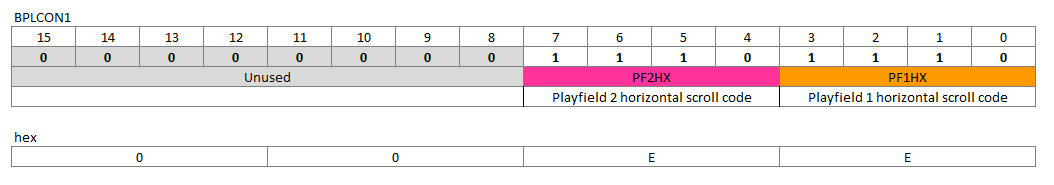
This demo is not using dual playfields, so we must use the same horizontal scroll value for both playfields. That’s why the $\$E$ is repeated and becomes $\$EE$.
The Code
I have added my own comments to the code below, just to give a rough outline of what is happening.
I recommend that you quickly read through the code, and then read the more in-depth stuff that follows.
start:
  move.w  #$4000,$dff09a  ; INTENA disable interrupts
  move.w  #$01a0,$dff096  ; DMACON disable bitplane, copper, and sprites

  lea.l   screen(pc),a1   ; move screen address into a1
  move.l  #$dff180,a2     ; move COLOR00 address into a2
  moveq   #3,d0           ; initialize loop counter d0 to 3
colloop:                  ; color loop
  move.w  (a1)+,(a2)+     ; copy from a1 (screen) to a2 (color table)
  dbra    d0,colloop      ; if d0 > -1 goto colloop

  lea.l   bplcop+2(pc),a2 ; move bplcop+2 address into a2
  move.l  a1,d1           ; move a1 (first bitplane in screen) into d1
  moveq   #1,d0           ; initialize loop counter d0 to 1
bplloop:                  ; bitplane loop
  swap    d1              ; swap words of d1
  move.w  d1,(a2)         ; set BPL1PTH to high 3 bits of bitplane address
  swap    d1              ; swap words of d1
  move.w  d1,4(a2)        ; set BPL1PTL to low 15 bits of bitplane address
  addq.l  #8,a2           ; increment bplcop pointer with 8
  add.l   #10240,d1       ; increment d1 to point at next bitplane in screen
  dbra    d0,bplloop      ; if d0 > -1 goto bplloop

  bsr.s	initcop           ; branch to subroutine initcop

  lea.l   copper(pc),a1   ; move copper address into a1
  move.l  a1,$dff080      ; move a1 into COP1LCH and COP1LCL

  move.w  #$8180,$dff096  ; DNACON enable bitplane, copper

wait:                     ; busy wait for beam
  move.l  $dff004,d0      ; move VPOSR and VHPOSR into d0
  asr.l   #8,d0           ; shift right 8 places
  andi.w  #$1ff,d0        ; keep first 9 bits vertical position of beam
  cmp.w   #280,d0         ; is beam at line 280?
  bne.s   wait            ; if not goto wait

  bsr.s   wave            ; branch to subroutine wave

  btst    #6,$bfe001      ; test left mouse button
  bne.s   wait            ; if not pressed goto wait

  move.l  $04.w,a6        ; make a6 point to ExecBase of exec.library
  move.l  156(a6),a6      ; IVBLIT points to GfxBase
  move.l  38(a6),$dff080  ; copinit ptr to copper start up list restore workbench copperlist

  move.w  #$8020,$dff096  ; DMACON enable sprite
  rts                     ; return from subroutine

initcop:                   ; initialize copper list
  lea.l	  wavecop(pc),a1   ; move wavecop address into a1
  move.w  #$4adf,d1        ; move copper wait for vpos >= $4a and hpos >= $de
  move.w  #199,d0          ; initilize loop counter d0 to 199
initcoploop:               ; add waits to wavecop
  move.w  d1,(a1)+         ; set wait - post incr. a1
  move.w  #$fffe,(a1)+     ; set wait mask - post incr. a1
  move.l  #$01020000,(a1)+ ; set BPLCON1 - post incr. a1
  add.w   #$100,d1         ; increment scanline by 1
  dbra    d0,initcoploop   ; if d0 > -1 goto initcooloop
  rts                      ; return from subroutine

cont:
  dc.w	0                  ; index into the sine table

wave:
  lea.l   cont(pc),a1       ; move cont address into a1
  move.w  (a1),d1           ; move cont value into d1
  addq.w  #2,(a1)           ; cont += 2
  andi.w  #$fe,d1           ; keep first word and allign it to an equal number
  lea.l   sin(pc),a1        ; move sin address into a1
  add.w   d1,a1             ; add the offset to the sine table
  lea.l   wavecop+6(pc),a2  ; move wavecop+6 into a2
  move.w  #199,d0           ; loop counter d0 = 199
waveloop:                   ; loop over 200 scanlines in copper
  move.w  (a1)+,(a2)        ; copy sine value to copper (set DFF102)
  addq.l  #8,a2             ; move to next scanline in copper
  dbra    d0,waveloop       ; if d0 > -1 goto waveloop
  rts                       ; return from subroutine

copper:
  dc.w	$2001,$fffe  ; wait for vpos >= $20 and hpos >= 0
  dc.w	$0104,$0000  ; move $0000 to $dff104 BPLCON2 video
  dc.w	$0108,$0000  ; move $0000 to $dff108 BPL1MOD modulus odd planes
  dc.w	$010a,$0000  ; move $0000 to $dff10a BPL2MOD modulus even planes
  dc.w	$008e,$2c81  ; move $2c81 to $dff08e DIWSTRT upper left corner ($81,$2c)
  dc.w	$0090,$f4c1  ; move $f4c1 to $dff090 DIWSTOP (enable PAL trick)
  dc.w	$0090,$38c1  ; move $38c1 to $dff090 DIWSTOP (PAL trick) lower right corner ($1c1,$12c)
  dc.w	$0092,$0038  ; move $0038 to $dff092 DDFSTRT data fetch start at $38
  dc.w	$0094,$00d0  ; move $00d0 to $dff094 DDFSTOP data fetch stop at $d0

  dc.w	$2c01,$fffe  ; wait for vpos >= $2c and hpos >= 0
  dc.w	$0100,$2200  ; BPLCON0 enable 2 bitplanes, enable color burst

bplcop:
  dc.w	$00e0,$0000  ; BPL1PTH (high bit 16-31)
  dc.w	$00e2,$0000  ; BPL1PTL (low  bit 0-15)
  dc.w	$00e4,$0000  ; BPL2PTH (high bit 16-31)
  dc.w	$00e6,$0000  ; BPL2PTL (low bit 0-15)

wavecop:
  blk.w	1600/2,0     ; allocate 800 words

  dc.w	$2c01,$fffe  ; wait for vpos >= $12c and hpos >= 0 (explained later)
  dc.w	$0100,$0200  ; BPLCON0 disable bitplane - older PAL chips.
  dc.w	$ffff,$fffe  ; wait indefinitely - until next vertical blanking

sin:
  blk.w	656/2,0

screen:
  blk.w	20488/2,0
Let’s break the program down into it’s important components.
The program starts by copying the colormap to the color registers and bitplane pointers into to the Copper list. It then goes into a loop that busy waits for the beam to reach scanline 280. This ensures that the wave subroutine is only called once per frame.
Last but not least, we check to see if the left mouse button has been pressed. If it has, the workbench Copper list is restored and the program terminates.
Lets look at the subroutines.
Initialize Copper
The initcop subroutine initializes horizontal shifting for 200 scanlines, by poking instructions into the memory allocated at the label wavecop.
initcop:                   ; initialize copper list
  lea.l	  wavecop(pc),a1   ; move wavecop address into a1
  move.w  #$4adf,d1        ; move copper wait for vpos >= $4a and hpos >= $de
  move.w  #199,d0          ; initilize loop counter d0 to 199
initcoploop:               ; add waits to wavecop
  move.w  d1,(a1)+         ; set wait - post incr. a1
  move.w  #$fffe,(a1)+     ; set wait mask - post incr. a1
  move.l  #$01020000,(a1)+ ; set BPLCON1 - post incr. a1
  add.w   #$100,d1         ; increment scanline by 1
  dbra    d0,initcoploop   ; if d0 > -1 goto initcooloop
  rts                      ; return from subroutine
For each of the 200 scanlines, it adds a wait followed by a move to the custom chip register BPLCON1, with the value $\$0000$. The wave subrotine will later overwrite them with sine values.
The horizontal scrolling effect requires smooth scrolling. We can’t achieve that by using the bitplane pointers and modulo, since it moves the screen horizontally in steps of 16 pixels (1 word).
Fine scrolling, in steps of one pixel, is done by using BPLCON1. It works by adding a delay to the output of pixel data, and can have a value from 0 to 15, where 0 is no shifting. At the largest value, the pixels are delayed, so that they are displayed 15 pixels later, than they otherwise would have. In other words, the pixels are shifted to the right.
There’s a good section on smooth scrolling in the Amiga System Programmer’s Guide.
The horizontal shifting starts at scanline $\$4A$ and ends 200 lines later. We can calculate where the effect starts and stops, by taking into account that the display window starts at $\$2C$.
The effect starts at image line (starting from 0): $$\textrm{start} = \$2C - \$4A = \$1E = 30$$
And ends at image line: $$\textrm{end} = \$1E + 200 = 230$$
I have added some grid lines to the next image, to illustrate that the upper and lower part of the image is not affected by the horizontal shifting effect.

Because of the way the effect has been coded, it will only look good if the image have thick black borders.
Update Sine Wave
The wave subroutine is responsible for poking sine values into the Copper list. It’s called once per frame and uses the counter cont to determine the start index into the sine table.
wave:
  lea.l   cont(pc),a1       ; move cont address into a1
  move.w  (a1),d1           ; move cont value into d1
  addq.w  #2,(a1)           ; cont += 2
  andi.w  #$fe,d1           ; keep first word and allign it to an equal number
  lea.l   sin(pc),a1        ; move sin address into a1
  add.w   d1,a1             ; add the offset to the sine table
  lea.l   wavecop+6(pc),a2  ; move wavecop+6 into a2
  move.w  #199,d0           ; loop counter d0 = 199
waveloop:                   ; loop over 200 scanlines in copper
  move.w  (a1)+,(a2)        ; copy sine value to copper (set DFF102)
  addq.l  #8,a2             ; move to next scanline in copper
  dbra    d0,waveloop       ; if d0 > -1 goto waveloop
  rts                       ; return from subroutine
The start index is stored in d1 and is and’ed with $\$FE$ to restrict it to the range of even numbers between 0 and 254. Using the start index, the sine values are copied from the table into the Copper list, for each of the 200 scanlines.
The wave subroutine requires a sine table that has room for 128 entries of possible values for the start index followed by 200 entries for the scanlines. Giving a total size of 328 entries, which is exaclty the size of the sine table.
The Copper List
The wave program uses the Copper to set up the screen, the display data fetch, and other initialization stuff. On top of this, the Copper also adds the horizontal shifts.
Being partly hardcoded, and partly generated by the subroutines initcop and wave, makes it hard to evaluate the coppper list. So why not expand it, as it would look at some given time in memory. Let’s dive in 😃
It is very instructive to see the Copper instructions in relation to the scanlines and DMA bus cyles, because it highlighs how easy it is to race the beam with the Copper, and also gives a precise indication of what happens when.
I’ve illustrated the DMA time slots allocations, using slots of varied width, only so that there is enough room to write the instructions. The width has nothing todo with timing length.
The first line of the Copper list, instructs the Copper to wait for the beam to reach scanline $\$20$, and wait until horizontal position $\$0$.
copper:
  dc.w	$2001,$fffe  ; wait for vpos >= 20 and hpos >= 0
  ...
Notice the no-op at the horizontal beam position 0 in the illustration of the DMA time slot allocation below.

Over at the English Amiga Board they pointed out, that this no-op is there because the Copper start need one extra cycle before the first instruction fetch. The Copper is then instructed to wait for the beam to reach scanline $\$20$ and slot 0.
The next couple of Copper instructions, sets up a 320 x 256 pixel display.
  ...
  dc.w	$0104,$0000  ; move $0000 to $dff104 BPLCON2 video
  dc.w	$0108,$0000  ; move $0000 to $dff108 BPL1MOD modulus odd planes
  dc.w	$010a,$0000  ; move $0000 to $dff10a BPL2MOD modulus even planes
  dc.w	$008e,$2c81  ; move $2c81 to $dff08e DIWSTRT upper left corner ($81,$2c)
  dc.w	$0090,$f4c1  ; move $f4c1 to $dff090 DIWSTOP (enable PAL trick)
  dc.w	$0090,$38c1  ; move $38c1 to $dff090 DIWSTOP (PAL trick) lower right corner ($1c1,$12c)
  dc.w	$0092,$0038  ; move $0038 to $dff092 DDFSTRT data fetch start at $38
  dc.w	$0094,$00d0  ; move $00d0 to $dff094 DDFSTOP data fetch stop at $d0
  dc.w	$2c01,$fffe  ; wait for vpos >= $2c and hpos >= 0
  ...
Because of the previous wait, these instructions are first executed by the Copper, when we reach scanline $\$20$. Here’s the DMA time slot allocation.

I have put a “W” at bus cycle 0, that belongs to the wait from scanline 0. The wait instruction requires 3 bus cycles - two for the command words, specifying the beam position to wait for, and an additional cycle before the beam position is reached.
The third wait cycle should be before the requested slot.
Waiting for slot 0 is an exception from the rule. Since there is no slot before slot 0, the bus arbitration logic puts the wait at slot 0, and push the fetch to slot 2. So in practice waiting for slot 0 or slot 2 of a certain line has the same effect.
The last Copper instruction on the scanline, is a wait for the beam to reach scanline $\$2C$. Without the waits, the Copper would just increment it’s program counter and read the next instructions.
It’s important to remember the waits, so that things happen at the correct beam positions, but also because while waiting the Copper is off the bus, which frees cycles for both the CPU and blitter.
We enable the two image bitplanes and set their pointers, with the following Copper instructions at scanline $\$2C$.
  ...
  dc.w	$0100,$2200  ; BPLCON0 enable 2 bitplanes, enable color burst

bplcop:
  dc.w	$00e0,$0000  ; BPL1PTH (high bit 16-31)
  dc.w	$00e2,$0000  ; BPL1PTL (low  bit 0-15)
  dc.w	$00e4,$0000  ; BPL2PTH (high bit 16-31)
  dc.w	$00e6,$0000  ; BPL2PTL (low bit 0-15)

wavecop:
  dc.w  $4adf,$fffe  ; written by the initcop subroutine
  ...
The instructions turns on bitplane data fetch for this, and the following scanlines. The PTL, PTH chip memory pointers must be reloaded after vertical blank, and that’s why the Copper must set them again on each run of the Copper list. The reason for this behavior, might be that these pointers are incremented while drawing the display. Here’s the DMA time slot allocation.

Again we start the scanline with the last cycle from the previous wait, followed by the rest of the Copper instructions. We finish by instructing the Copper to wait for the beam to reach scanline $\$4A$ at $\textrm{hpos} >=\$DE$.
The last wait is written to the Copper by the initcop subroutine. For the next 200 scanlines, it will insert a wait followed by a call to BPLCON1 initialized to $\$0000$. This value is later updated continously by the wave subroutine, with data from the sine table.
Here are some of those 200 scanlines.
  ...
  dc.w  $0102, $0000  ; BPLCON1
  dc.w  $4BDF, $FFFE  ; wait for vpos >= $4B and hpos >= $DE
  dc.w  $0102, $0000  ; BPLCON1
  dc.w  $4CDF, $FFFE  ; wait for vpos >= $4C and hpos >= $DE
  dc.w  $0102, $0000  ; BPLCON1
  dc.w  $4DDF, $FFFE  ; wait for vpos >= $4D and hpos >= $DE
  dc.w  $0102, $0000  ; BPLCON1
  ...
I have only shown the initial values of BPLCON1, before they are updated by the wave subroutine. Here’s the corresponding DMA time slot allocation.
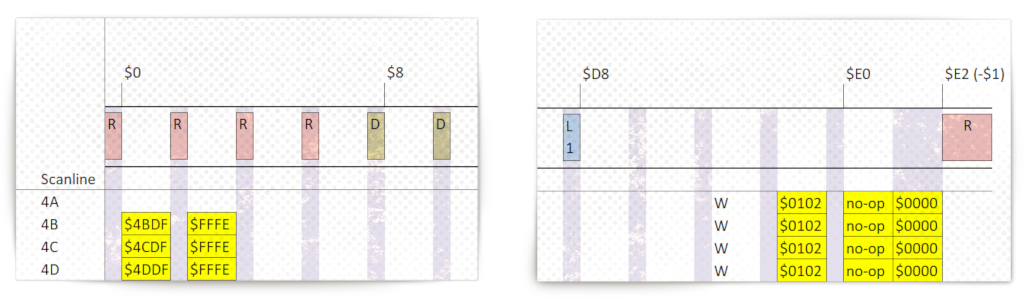
The value for BPLCON1 are set at the end of scanline $\$4A$, which means that the next scanline $\$4B$ is shifted horizontally. This pattern repeat itself for the next 200 scanlines, to create the scrolling effect. 👍
The next wait appears at the start of scanline $\$4B$, because there were no available slots left at the previous scanline.
Can the Copper use uneven slots? (PAL only)
The Copper can only use even slots, but PAL timing makes slot $\$E0$ a special slot, that can’t be used by the Copper. If you setup the Copper to use it, it will input a no-op and continue on to $\$E1$ which is uneven. The cycle at $\$E0$ is wasted.
Slot $\$E2$ can’t be used by the Cooper, since it becomes slot $-\$1$, which is the start of the next scanline.
If we change the Copper list of the wave program to avoid $\$E0$, we would win 200 DMA cycles per frame for other uses.
Se more about this at the English Amiga Board.
The horizontal scroll effect ends with the following Copper instructions.
  ...
  dc.w  $11DF,$FFFE  ; wait for vpos >= 111 and hpos >= $DE
  dc.w  $0102,$0000  ; BPLCON1
  dc.w	$2c01,$fffe  ; wait for vpos >= 12c and hpos >= 0
  ...
The effect ends at scanline $\$112$, which is given as $\$12$ because the $\textrm{vpos}$ counter rolled over when it went past scanline $\$FF$.

On scanline $\$112$, the Copper is instructed to wait for scanline $\$12C$, which is written as $\$2C$ because of counter rollover.
At scanline $\$12C$ the bitplanes are disabled.
  ...
  dc.w	$0100,$0200  ; BPLCON0 disable bitplane - older PAL chips.
  dc.w	$ffff,$fffe  ; wait for vpos >= $FF and hpos >= $FE
                     ; wait indefinitely - until next vertical blanking
The instruction will stop bitplane data fetch, which frees up bus cycles for the CPU and blitter. The wait instruction is a bit special.

The first cycle on scanline $\$2C$ is the last wait cycle from the previous wait. After disabling the bitplanes, the scanline ends by waiting for slot $\$FE$ at scanline $\$FF$. The beam will never reach this slot, since the last possible slot is $\$E2$ and the Copper will be forced to wait indefinitely.
The Copper list is restarted, when the Copper program counter is reset back to it’s value given in COP1LC, which happens at every vertical blanking, regardless of the Copper was finished or not with it’s previous list.
Extra Work
The wave program can only handle two bitplanes, which reduces the palette to only four colors. It would be fun with more colors, so go ahead and modify the progam to use five bitplanes.
Here’s an example of how cool this effect can look with the right graphics! ❤️

The image is of King Tutankhamun and painted by Avril Harrison. It’s an iconic Amiga artwork, well known from Deluxe Paint, where it was used in commercials and as box cover art 🎨.
Final Thoughts
We’ve covered a lot of ground in this post. Most importantly, we scratched the surface of what bus arbitration is, and how it avoids bus contention, by instructing the “two computers” inside the Amiga to work together when accessing the shared chip mem.
There’s an excellent DMA debugger in WinUAE / FS-UAE, that I used when visualizing the DMA time slot allocations. If time allows, I’ll write about this in a future post.
Have fun! 😃
Previous post: Amiga Machine Code Letter XII- The Starfield Effect
Next post: Amiga Machine Code Letter XII- Line Drawing